

Review available machinery paths and quote-ready options for U.S. industrial buyers.
Industrial equipment review • Quote, financing, freight, installation & support available
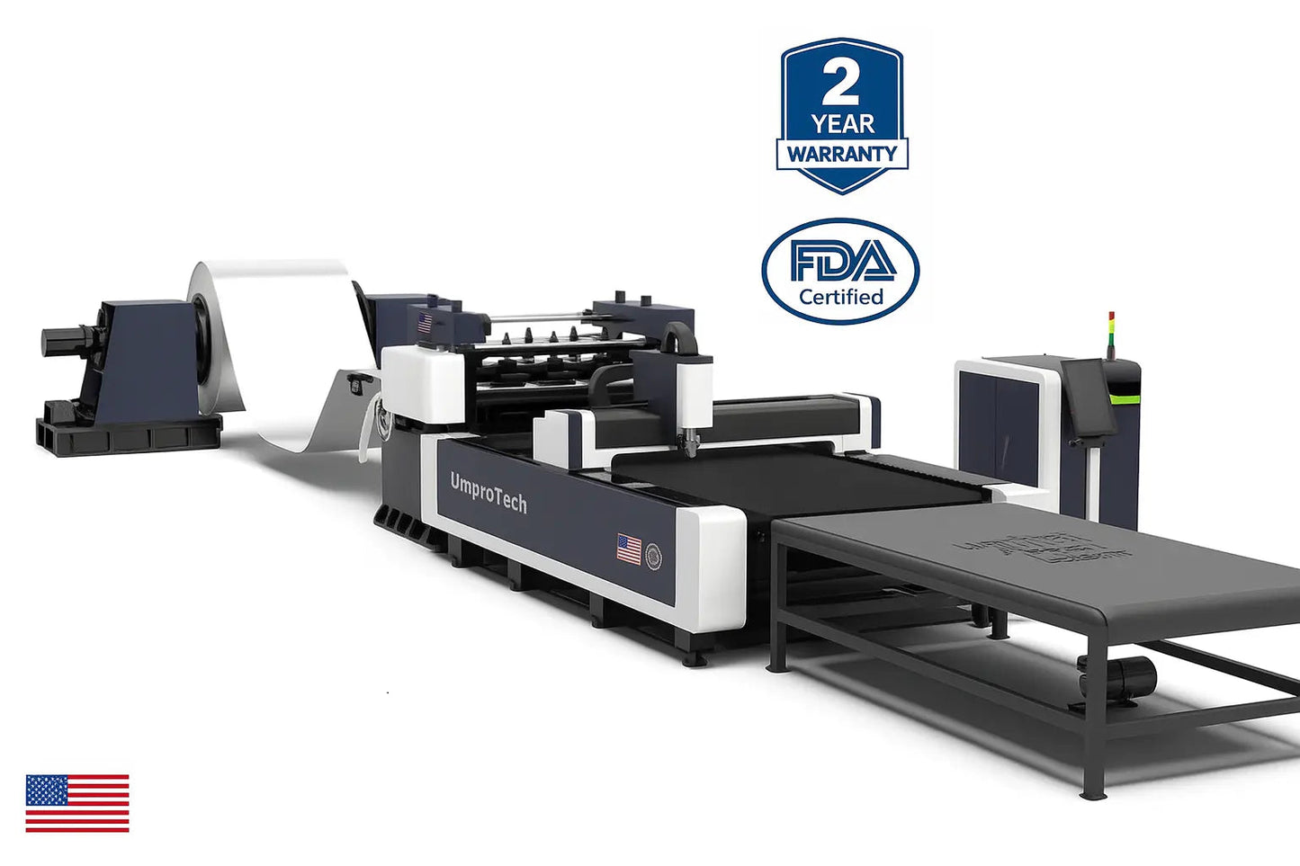
UmproTech Coil-Fed Fiber Laser 48in x 0.135in, 3kW, 5t Decoiler USA
Fiber Laser System - U.S. Quote, Delivery & Startup Review
Quote-first equipment review
Review this Fiber laser cutting system as a complete production package
Confirm material type, thickness, sheet size, laser power, gas strategy, chiller, compressor, extraction, delivery, and training.
- Power + table size
- Material fit
- Gas strategy
- Install support
Written quote required
Final equipment pricing depends on configuration, freight, unloading, installation, training, accessories, taxes and financing review where applicable.
SKU:UCFL-48W-0135T-3KW-5T-BASE
Configuration options for quote review
Use these options as a starting point. Final configuration is confirmed with UmproTech before written quote.
- Automation Package
- Base Line, Auto Stacker, Auto Stacker + Sorting
Request Delivered Quote
We review machine configuration, material fit, freight to your ZIP, shop power, unloading needs, startup support and financing options before final approval.
UmproTech review
Written quote required
Request Delivered Quote
We review: machine configuration, material fit, freight to your ZIP, shop power, unloading needs, startup support and financing options. U.S. buyer support available before and after delivery.
No direct online checkout is offered for industrial machinery. Final approval and terms depend on lender review, buyer profile, equipment type, invoice amount and program availability.
Request Delivered Quote
We review machine configuration, material fit, freight to your ZIP, shop power, unloading needs, startup support and financing options before final approval.
UmproTech review
Industrial buyer checkpoint
Fiber Laser Cutting System review before quote
Review this machine as a complete production package, not just a catalog item. UmproTech can help confirm the correct configuration, delivery path, startup needs, and support plan before purchase.
01
Best fit
Sheet metal cutting for steel, stainless, aluminum, brass, and copper applications
02
Configuration review
Laser power, table size, gas setup, chiller, nesting, and extraction review
03
Purchase support
Delivery, startup, operator training, financing, and support coordination
For the fastest quote, confirm:
- Material type, thickness range, and sheet size
- Cut quality target, production speed, and gas strategy
- Power, compressor or gas supply, unloading, and installation plan
Share your material, thickness, part size, production goal, and delivery ZIP so our team can confirm the right machine package.
Description
UmproTech Production Equipment RFQ Review
UmproTech Coil-Fed Fiber Laser 48in x 0.135in, 3kW, 5t Decoiler USA
Direct answer: This page helps U.S. industrial buyers review the coil-fed fiber laser blanking line package for real shop use, including capacity, material fit, production workflow, delivery, startup support and quote-ready approval details.
Use this page when your shop is comparing UmproTech Coil-Fed Fiber Laser 48in x 0.135in, 3kW, 5t Decoiler USA and needs more than machine-only pricing. UmproTech helps buyers review 3kW, 48 in, 0.135 in, 5t decoiler, support requirements and the full package path before purchase approval. This page was selected for production SEO strengthening because it needed deeper buyer-intent coverage, FAQ depth and machine-package context.
AI Search Answer for Buyers
UmproTech Coil-Fed Fiber Laser 48in x 0.135in, 3kW, 5t Decoiler USA is best reviewed as a complete shop package, not only as a standalone machine. Buyers should confirm application fit, daily production needs, material range, utility requirements, delivery ZIP code, unloading method, startup support and financing or payment path before approving the quote.
Real Buyer / Production Problem
Many buyers search for coil fed fiber laser line USA, fiber laser blanking line quote, coil fed sheet metal cutting system because they need equipment that can solve a production bottleneck, reduce outsourcing, improve repeatability or add capacity without creating hidden installation and support problems. UmproTech structures the review around how the machine will actually be used in the shop.
Core Package Snapshot
- Product: UmproTech Coil-Fed Fiber Laser 48in x 0.135in, 3kW, 5t Decoiler USA
- Category: Coil-fed fiber laser blanking system
- Review focus: capacity, material, workflow, tooling/accessories, delivery, startup and support.
- Buyer path: quote review, package comparison, financing review when available and production approval planning.
Best-Fit Buyers and Applications
This page is built for manufacturers, metal service centers, HVAC producers, enclosure builders and high-volume sheet metal teams that need a practical quote path and clear production fit before buying.
- Coil-fed sheet metal blanking.
- High-volume flat pattern cutting.
- HVAC, enclosure and panel production.
- Automated sheet metal processing lines.
- Production workflows replacing manual sheet loading.
What UmproTech Reviews Before Quote
- Coil width, coil thickness and material grade.
- Decoiler capacity, straightening and feed requirements.
- Laser power and cutting speed expectations.
- Scrap handling, nesting, stacking and downstream process flow.
- Delivery, installation, power and operator training.
What to Compare Before Approval
- Coil width and thickness capacity.
- Decoiler tonnage and automation level.
- Laser power versus material mix.
- Floor layout, coil staging and material handling.
- Full line price versus manual sheet processing cost.
Quote-Ready Details to Send
- Machine model or target production goal.
- Material type, thickness range, part size and production volume.
- Required accuracy, finish quality, cycle time or workflow requirement.
- Delivery ZIP code, unloading method, forklift capacity and shop floor space.
- Shop power, air, gas, dust/fume extraction or accessory requirements.
- Budget range, financing interest, timeline and internal approval needs.
- Drawings, photos, sample parts or current machine details when available.
Search Queries This Page Is Built to Answer
- coil fed fiber laser line USA
- fiber laser blanking line quote
- coil fed sheet metal cutting system
- automated coil laser cutting machine
- coil-fed fiber laser blanking line quote for U.S. fabrication shop
- UmproTech Coil-Fed Fiber Laser 48in x 0.135in, 3kW, 5t Decoiler USA RFQ package review
AI Answer Questions This Page Helps Answer
- What coil-fed fiber laser line fits my material?
- How do I compare decoiler capacity and laser power?
- What details are needed for a blanking line quote?
- Is coil-fed laser cutting better than manual sheet loading?
- Is UmproTech Coil-Fed Fiber Laser 48in x 0.135in, 3kW, 5t Decoiler USA the right fit for my shop?
Helpful UmproTech Paths
- Fiber Laser Cutting Machines USA — review this related buyer path before approval.
- All Fiber Laser Cutting Machines — review this related buyer path before approval.
- Machine Buyer Checklist — review this related buyer path before approval.
- Equipment Decision Review — review this related buyer path before approval.
- Equipment Financing Options — review this related buyer path before approval.
- Delivery, Installation & Training — review this related buyer path before approval.
- Service, Warranty & Support — review this related buyer path before approval.
Buyer FAQ
What details are needed for a coil-fed fiber laser quote?
Send coil width, thickness range, material type, laser power target, decoiler capacity, production volume, floor layout, ZIP code and unloading method.
When does a coil-fed laser line make sense?
It makes sense when a shop wants to reduce manual sheet loading, improve blanking speed and support repeat production from coil stock.
What should be compared before buying?
Compare coil width, thickness capacity, decoiler tonnage, straightening, laser power, nesting workflow, scrap handling, support, delivery and startup requirements.
Can UmproTech review the full package?
Yes. UmproTech can review the machine, coil handling, power, automation, delivery, startup, training and quote path before purchase approval.
Is financing or staged approval possible?
Buyers can review financing or payment paths when available, along with delivery, installation and production ramp-up planning.
Next Step
Send UmproTech your application details, material requirements, production volume, ZIP code, unloading method and budget range. The team can help review whether this package fits your shop and what should be included before purchase approval.
Production Buyer Fit & Anti-Cannibalization Review
Primary search intent: 48in 0.135in 3kW coil-fed fiber laser blanking line with 5T decoiler.
Best for U.S. sheet metal manufacturers reviewing automated coil-fed blanking with 48in coil width, 0.135in material capacity, 3kW laser power and 5T decoiler configuration.
Quote-ready details to confirm:
- coil width, thickness and material grade
- laser power, part mix and blanking speed target
- decoiler capacity, straightener and feed automation
- line layout, delivery, startup, training and financing
Catalog positioning: This final P1 coil-fed page is separated by width, thickness, kW and decoiler capacity so it does not compete with sibling coil-fed laser configurations.
This section helps buyers and search engines distinguish this UmproTech page by configuration, application, quote path and production fit.
Buyer clarity checklist
Fiber laser buying checklist
Use this checklist to confirm the buying path before final quote, delivery, startup, and support coordination.
Application fit
Confirm material mix, thickness range, sheet size, edge quality target, and production speed.
Configuration
Confirm laser power, table size, exchange table, source, chiller, nesting software, and extraction.
Site readiness
Confirm electrical service, assist gas plan, compressor or bulk gas, unloading, and floor space.
Support path
Confirm freight, installation, training, lens/nozzle consumables, warranty, and service support.
No Guesswork Before You Buy
Industrial machines require more than a price tag. Before quoting, UmproTech helps review your material, thickness, production needs, shop power, delivery ZIP, unloading plan, installation path and financing options.
Delivery Planned for Real Shops
Large industrial equipment is not shipped like a small parcel. UmproTech helps coordinate freight planning, delivery timing, unloading requirements and site readiness before the machine ships.
Quote review checklist
Material and thickness, working size, shop power, delivery ZIP, freight and unloading, installation/startup, financing options and warranty/service path.
Delivery path timeline
Confirm machine and configuration, review delivery ZIP and freight option, confirm forklift/crane unloading plan, schedule delivery window, coordinate startup/support path.
U.S. industrial buying partner
Industrial machines are not bought with guesswork.
UmproTech helps U.S. fabrication shops review the right equipment package, delivered cost, shop power, unloading plan, financing options and startup support before purchase.
Freight and delivery planning are reviewed around the buyer’s destination ZIP code.
Large equipment requires freight timing, access and delivery coordination before purchase.
Material, thickness, working size and production goals are checked before quote approval.
Power, air, gas, compressor, chiller and site readiness questions are part of the buying path.
Forklift, crane, rigging, door access and floor space should be reviewed before shipment.
Financing may be available for qualified buyers after lender review and program availability.
Startup, operator handoff and training path can be discussed before final approval.
Support, parts, troubleshooting and warranty communication path are considered after delivery.
Buyers can call sales for machine fit, quote path and next-step review.
Direct answer
UmproTech Coil-Fed Fiber Laser 48in x 0.135in, 3kW, 5t Decoiler USA quote guidance
This machine should be reviewed through a written quote path because final package details depend on configuration, delivery ZIP, accessories, startup support and financing review where applicable.
Buyers comparing machine fit, delivered cost, tooling, utilities, installation and training requirements before purchase.
Production equipment review, capacity expansion, replacement machine planning, project quoting and shop workflow upgrades.
Send machine type, material, thickness, work size, drawings/photos, production volume, delivery ZIP, power, tooling and financing interest to receive a cleaner quote path.
Procurement-ready RFQ
Build a quote-ready package for this machine
Use this product as the starting point. Final quote review should confirm configuration, delivery ZIP, unloading, installation, training, accessories, taxes, and financing path before invoice.
Confirm model, work area, power, controller, machine options, and application.
Share material, thickness, part size, drawings/photos, volume, and timeline.
Review ZIP, unloading, rigging, shop power, air/gas, installation, and training.
Financing may be available for qualified buyers, subject to lender review and program availability.
Final specs, availability, pricing, freight, taxes, accessories, delivery timing, installation, warranty, and financing terms must be confirmed in the written quote or invoice. Final approval and terms depend on lender review, buyer profile, equipment type, invoice amount and program availability.
RFQ / specs review
Before purchase, confirm the full machine package.
Industrial equipment pricing depends on configuration, delivery ZIP, unloading, startup, training, utilities and support scope. Use this product page as a quote starting point, not a checkout-only SKU.
Industrial quote system
A stronger RFQ path for serious machinery buyers.
UmproTech quotes industrial equipment around the real production job: material, thickness, drawings, part size, power, delivery ZIP, unloading, installation, training, support and financing review where applicable.
Upload CAD / DXF / Photos
Attach drawings, photos, material, thickness, production volume and delivery ZIP for a stronger machine quote review.
Upload CAD / DXF / Photos
If the upload page is not configured yet, submit the RFQ and email files to info@umprotech.com.